Tools Used/ BOM
- $20 | 2x Arduino
- $2 | 2x Breadboard
- (incl.) | 2x Servo Motor + library
- $65 | Pixy Camera 2 + library + Pixymon
- $10 | 2x HC-05 Bluetooth Modules
- $250 | Parallax BOE Shield
- $2.50 | PS2 Joystick
- $5 | LCD with Backpack + library
- $0 | Jumper Wires
- $0 | A Few Resistors
- $$$ | A Lotta Patience
- PID, I2C libraries
Total: $354.50
(realistically this is much cheaper without buying the BOE, a realistic amount would be ~$100)
Overview
doggie is wireless object tracking robot which was made for my circuits final project. it can be used to find or track certain objects where humans may either be too large or unable to physically track items (think bomb squad or arctic research, or even mars rover stuff)
using the remote control you use the joystick to select which preloaded object to search for with the lcd. once you choose which object to search for the doggie is is set to detect and track/follow that object using PID control system, without being distracted by other objects in its memory
Assembly
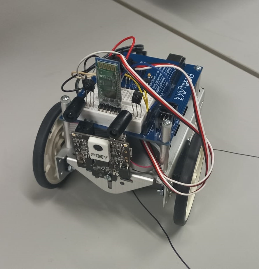
most of the assembly was already taken care of since i used the parallax boe shield as my chassis, however there were some modifactions made. the pixy camera was placed in front of the robot and is screwed in (i also had to deconstruct and reassamble the robot to reach the arduino in order to plug the pixy's spi cable into the arduino. i also swapped the prebuilt wheels for thicker rubber wheels since the original ones had very little traction causing the robot to perform horribly on turns
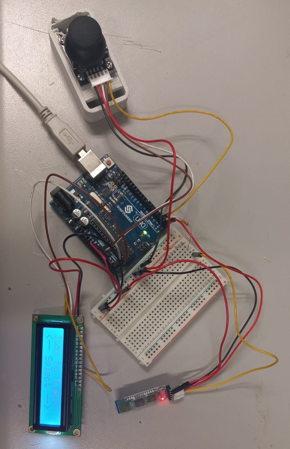
unfortunately wasnt able to prototype a shell for the remote control so its just kinda naked there and has definitely come undone in storage
Wiring
on the doggie wiring was done through the boe's built-in breadboard. however its important to note that since the pixy is connected via spi digital pins 10, 11, 12, and 13 are occupied on the arduino. so the pins the servos were originally connected to had to be switched to available pins. also 0 and 1 (RX and TX) are wired to the hc05 for UART commication. the hc05s also make use of a voltage divider with the resistors in order to bring the voltage down to 3.3v since thats what they operate on. and luckily the lcd had a backpack for i2c communication so i didnt need to fiddle too much with all the pins on that.
other than that the rest of the wiring is pretty standard except for the IR sensors, which arent wired to anything. originally they were connected to the arduino on doggie but i found that they would work well since their minimum range was the pixy's maximum practical range. they looked like eyes tho so i left em on
Programming
both programs (one each for the remote and doggie) come in under 100 lines each thanks to libraries so the programming was pretty light
starting with the remote we initialize the lcd in the setup, then clear it in the beginning of the void loop. the joystick position and button are then read and after a check is done to see if the user moved the joystick to browse items to select. it will load the next page if the user moved right/left on the joystick and display the item to search for on the page. after it checks to see if the user pressed the button on an item page and if that happens it will let the user know theyve selected an item. after this information on which item has been selected is sent over the serial via the hc05 and read by the doggie
now with the doggie first it intializes everything like servos, PID params, and pins. in the setup we begin the serial communication at 9600 baud and initialize the pixy, pid, and servos. before the main program we also have two functions thatll be used later: setMotorSpeeds and stopRobot, both of which are pretty self explanatory. setMotorSpeeds uses the output from the PID feedback to set the motor speeds of the servos, however since the servos are in opposite directions the speeds have to be inverted. additionally the servos go from 1300 (backwards) to 1500 (stop), to 1700 (forward) so this was pretty confusing for a bit. moving onto the main program it waits until a signal is recieved via bluetooth and when it recieves a signal, it sets the blockType (block it searches for) to the color signature its searching for.
more in depth on the pixy but i has built in object detection since the arduino doesnt have enough juice to do so itself. the object detection on the pixy is pretty basic but basically there are several color signatures it works with and references color as well as shape to determine objects (which are set in the pixy's own software)
the pixy camera then looks to first see if there are any objects in its view. if so, it checks to see if the object is at a safe distance and the color signature matches the one its searching for. with that it inputs the x-coordinate of the object which the pid uses to get error and set motor speeds. and yah das it :)
Challenges
so there were a lot of challenges, and i spent way too long trying to fix so many issues that i though were software related that were actually simple hardware issues
the first that comes to mind is the pixy-servo issue. at the time i didnt realize it but when connecting the pixy to the arduino it takes up the SPI communication pins which are 10, 11, 12, and 13. but because these arent physically occupied i assumed i could still used them, so i left the motors plugged into them (which was their default configuration). i kept testing my code wondering why only one would work at a time before stumbling upon some forum post letting me know i was being stupid
a smaller issue now but intially i wanted to use both the pixy and IR sensors to detect when the object wouldve been too close to the doggie so it stops. didnt have too many issues wiring and programming it but i found that the ir sensors minimum range (zone 0) had a range up to around a foot and a half in front of it, but also the pixy camera (because of poor lighting) had an effective range of about that much. so i had to sacfrifice the IR sensors to have the pixy work. kinda sucks because the wall detection i used with the pixy (checking to see if the object is too large) isnt very consistent, again because of lighting
now onto the bluetooth. omfg there were so many issues with the bluetooth. i think i spent maybe 12 hours fixing bluetooth issues (you cant imagine the serotonin rush i got each time i solved one of the issues)
the first of the issues came with getting the modules connected. this also roles into the 2nd issue but starting with this, a lot of sources i was looking at (mainly chatgpt) kept telling me a steady light meant the two modules were connected, however unbeknownst to me my modules signaled a steady connection with an unsynchronized double blink. not the most intuitive tbh. i spent a few hours debugging with AT commands and even setting them up was hard because they were incorrectly wired to begin with. because of the way serial communcation works with arduinos, firuging out when to switch TX and RX was a pain in the ass. i swap them when theyre in use, but when debugging i have to wired RX to RX, TX to TX, but when uploading the code since im using 0 and 1 ive just got to take them out ??? yo who the hell designed this why would they make it so counterintuitive :sob: and then plug the enA pin when debugging and remember to unplug it when in use also threw me off OD
and then there was the wiring issue. this was more my fault for being lazy and not following a proper wiring tutorial, but i was rawdogging the hc05s and didnt realize it relied on 3.3v and needed me to place some resistors to step down the voltage. although this wasnt very detailed this issue took a good four hours to solve (i think im cooked chat)
Reflection
although i spent way too much time on simple issue i had a lot of fun doing this project. it was such a nice feeling to see it simply working and i just wish i had a better presentation for the remote
this was also somewhat like vindication for me in highschool since in senior year we had a project involving lcds, bluetooth, and joysticks which i was never able to complete. so im glad i was able to do what me three years ago wasnt able to
next time around im definitely looking up wiring tutorials and gonna try to reduce my reliance on chatgpt, especially for anything hardware related. thats really where it falls flat
sidenote im really glad i was able to apply several concepts from class into this project, even though it intially seemed like more of a programming project than anything. votlage division and damping were some of the things i had to remember here and it was really motivating to see these put in use